

This online engineering tool is designed for overcurrent relay curve analysis (ANSI 50/51) and thermal relay modeling (ANSI 49). It accurately calculates the relay operating time according to IEC 60255, simulates trip behavior, and analyzes time–current characteristics.
Using this protection curve analyzer, you can simulate the real behavior of protection relays under overcurrent and overload conditions, and optimize TMS and pickup current settings for proper coordination.
Overcurrent relays utilize inverse-time characteristics to ensure selective and reliable equipment protection. This Engineering Calculator computes the relay operation for any given time instant () and current () using the following standard formula:
Where represents the ratio of the actual primary current to the relay pickup current:
This tool acts as a digital numerical simulator, replicating the logic of modern digital relays. It does not merely perform a static calculation; instead, it functions as a digital integrator. When the current exceeds the pickup threshold, the relay begins the process of “time accumulation.”
At each time interval (), the tool calculates the following ratio:
This value represents the “percentage of trip time accumulated” during that specific time step. Once the cumulative sum (the integral) reaches (or ), the relay issues a trip command. This methodology accurately mimics the real-world performance of numerical relays in complex power system protection schemes.
The thermal model in this tool is designed based on IEC standards for overload protection. Unlike a relay with a fixed time, the thermal model operates on stored energy:
This tool treats the equipment’s temperature or thermal capacity as a “tank.”
The equipment temperature rise is modeled using a first-order differential equation:
In the table, enter the time intervals () and the currents () corresponding to those moments.
Technical Note: This tool acts as a numerical simulator. Using smaller time steps ()—for example, second instead of seconds—will significantly increase the accuracy of the integral and thermal calculations.
| Time (ms) | I1 (A) | I2 (A) |
|---|---|---|
| Time(ms) | I1 | I2 | Ieq | Thermal % |
|---|
| Time(ms) | I1 | Relay Time(s) | Δt(s) | Δt/t | Integral | Status |
|---|
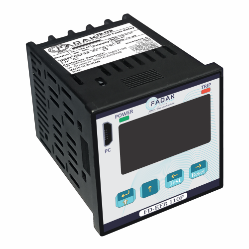
The FD-EFR110P Earth Fault Relay is engineered for highly accurate protection in electrical systems. Using advanced signal-processing techniques, it detects both transient and intermittent earth-fault conditions.
This relay prevents leakage currents and significantly enhances electrical safety by reducing the risk of damage, hazards, and downtime.
Features & Capabilities:
85–260V AC/DC power supply
Digital input for test/reset
1.3" OLED graphical display
Mini USB-B computer interface
Comes with dedicated configuration software
Low power consumption
Available in Lite & Pro versions
Fault waveform recording
Event logging
Transient & intermittent fault detection
Full support for standard protection curves
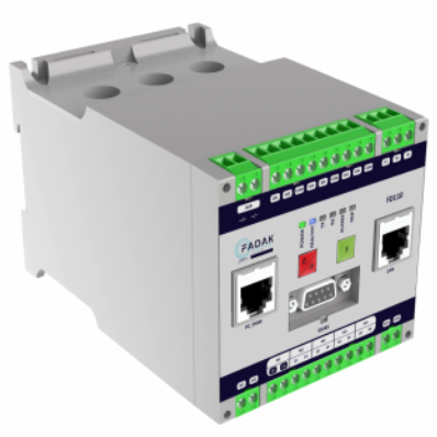
The FD110 Super Induction Motor Controller provides comprehensive and advanced motor protection and management. With precise monitoring and fault diagnosis capabilities, it prevents unwanted shutdowns and ensures stable motor performance. FD110 is suitable for various industrial motors and offers a reliable solution for optimizing operations.
Protection Features:
Overload Protection: Supports class 5 to 40
Overcurrent Protection: IEC standard protection curves
Phase Imbalance & Negative Sequence Protection to prevent abnormal operation
Earth Fault Protection: Supports CBCT or I0 summation methods
Startup & Operating Protection: 48/51LR
Undercurrent Protection to detect abnormal load conditions
Control & Measurement Features:
Compatible with various motor starting methods (Star-Delta, Dahlander, Forward-Reverse)
Built-in timer for advanced motor control
RTD measurement for accurate motor temperature monitoring
4–20mA analog output for integration with control systems
RS485 Modbus communication for industrial monitoring and control
Input/Output Specifications:
Power Supply: 85~260V AC/DC
6 digital inputs, 5 digital outputs
Direct connection up to 100A (above 100A requires external CT)
Key Advantage:
This system provides a complete solution for motor monitoring and protection, enabling optimal management and increasing system reliability.

