

Induction motors are widely used in industrial applications such as pumps, fans, compressors, and conveyor systems due to their robustness, cost‑effectiveness, and low maintenance requirements. However, in real industrial environments these machines are often exposed to harsh operating conditions, voltage disturbances, unbalanced loading, and equipment aging. Such conditions can lead to various electrical and mechanical faults. Detecting the early signs of these faults is therefore essential to prevent unexpected shutdowns and costly downtime. One of the most effective techniques for monitoring motor health and performing induction motor fault diagnosis is stator current monitoring, particularly Motor Current Signature Analysis (MCSA). Faults such as rotor mass unbalance or supply voltage unbalance can introduce characteristic variations in the current waveform and increase asymmetrical components in the stator current.
In practical industrial systems, these faults may occur simultaneously. When this happens, their combined effects can be more severe than single‑fault conditions and can significantly affect the reliability of the machine. Therefore, accurate induction motor fault diagnosis under combined fault conditions is an important topic in modern condition monitoring.
In this study, the simultaneous effects of rotor mass unbalance and voltage unbalance in an induction motor are experimentally investigated. To improve the induction motor fault diagnosis process, the analysis is performed not only using the conventional MCSA method but also through spectral analysis of Park’s vector components (Id and Iq). The results demonstrate that combining stator current analysis with Park’s vector analysis provides a powerful approach for accurate induction motor fault diagnosis, particularly for identifying combined faults and determining the faulty phase under unbalanced operating conditions.
Motor Current Signature Analysis (MCSA) is one of the most widely used techniques for induction motor fault diagnosis and forms the basis of many modern motor condition monitoring studies.
In this approach, the stator current signal is transformed from the time domain to the frequency domain using the Fast Fourier Transform (FFT). This transformation allows analysts to extract the spectral information of the current signal and identify frequency components associated with specific faults.
The main objective of this step is to identify characteristic frequencies that indicate a particular fault in the motor. In the frequency spectrum, each type of fault—such as unbalance, broken rotor bars, or voltage disturbances—appears as distinct frequency peaks. These spectral components serve as diagnostic indicators and play a key role in induction motor fault diagnosis using MCSA.
The Park transformation, first introduced by Robert Park in 1929, is a powerful analytical tool that simplifies a three‑phase system into two orthogonal components. By applying this transformation, the three stator phase currents , and are converted into the direct and quadrature components and :
In this transformation, represents the direct component of the current, while represents the quadrature component.
According to previous research, the Park vector contains the complete information of the three‑phase stator currents. Spectral analysis of the and components under healthy and faulty conditions has shown that the component alone carries most of the essential system information. Therefore, analyzing the spectrum of can provide clearer fault signatures and improve the reliability of induction motor fault diagnosis compared with classical current spectrum analysis.
In a mechanical mass unbalance fault, the mass distribution around the rotor’s axis of rotation is not uniform. This phenomenon can result from manufacturing imperfections, shaft misalignment, or shaft bending caused by thermal expansion.
Mass unbalance produces an unwanted centrifugal force acting on the rotor, which leads to mechanical vibration and torque oscillations during operation. These oscillations introduce harmonic components in the stator current at characteristic frequencies given by:
frequency component caused by mass unbalance =
supply frequency (typically 50 Hz) =
rotor rotational frequency =
These characteristic frequencies are important indicators used in induction motor fault diagnosis, especially when applying MCSA for detecting mechanical unbalance conditions.
Voltage unbalance is one of the most common phenomena in three‑phase power systems and occurs when the magnitude or phase angle of the voltages deviates from the ideal balanced condition. This situation increases losses, reduces torque, and lowers the efficiency of the induction motor.
In spectral analysis, this fault appears as sidebands in the stator current spectrum, which can be calculated using the following relationship:
where is the frequency component caused by the voltage fault and
For example, in experimental studies with a 20 V drop in one phase, a sideband peak was observed at 150 Hz, indicating the presence of voltage unbalance.
Standard references provide different definitions for measuring and expressing the degree of voltage unbalance.
where is the average line voltage:
with
The true definition of voltage unbalance is given as the ratio of the negative-sequence to positive-sequence components:
where and are the positive- and negative-sequence components obtained from the Fortescue transformation:
where
Similarly, current unbalance is defined as the ratio of the negative-sequence to positive-sequence current components:
Here, and are the positive- and negative-sequence components of the stator current, respectively.
These components are calculated using the following matrix relation:
The researchers designed a test bench to introduce the target faults into the induction motor and detect them through stator current analysis.
The same experimental platform had also been used in their previous studies.
In those works, the researchers separately investigated faults such as mechanical unbalance, voltage unbalance, broken rotor bars, and bearing defects. However, the study of combined faults—mechanical and electrical faults occurring simultaneously—represents a new approach, and this work adds it to the scientific literature in this field.
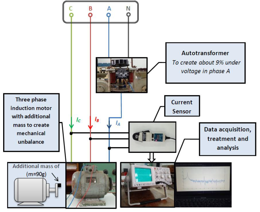
The main components of the experimental system were as follows:
Three-phase induction motor with the following specifications: 270 W, 50 Hz, Y connection, 220 V rated voltage, 1.43 A rated current, two pole pairs, and 1400 rpm.
Artificial mechanical unbalance was created by attaching an additional mass of to a disk mounted on the rotor shaft.
The voltage unbalance was created using the following procedure:
In the reported experiment, the RMS voltage of phase A was reduced by approximately 9% (slightly above 9%, but negligible).
Stator currents were measured using a current sensor and a HAMEG 507 digital oscilloscope equipped with a datalogger card, then transferred to a computer.
Data processing:The data were processed using MATLAB.
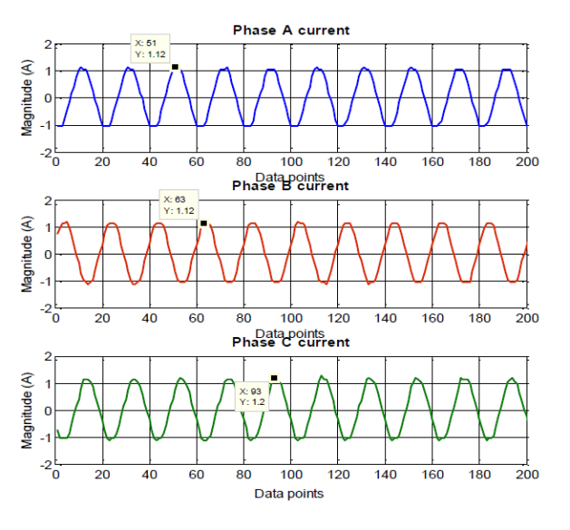
As illustrated in the corresponding figures, the three phases are nearly balanced and the current amplitudes are almost identical. Therefore, the motor operates in a healthy condition with no significant electrical or mechanical disturbances.
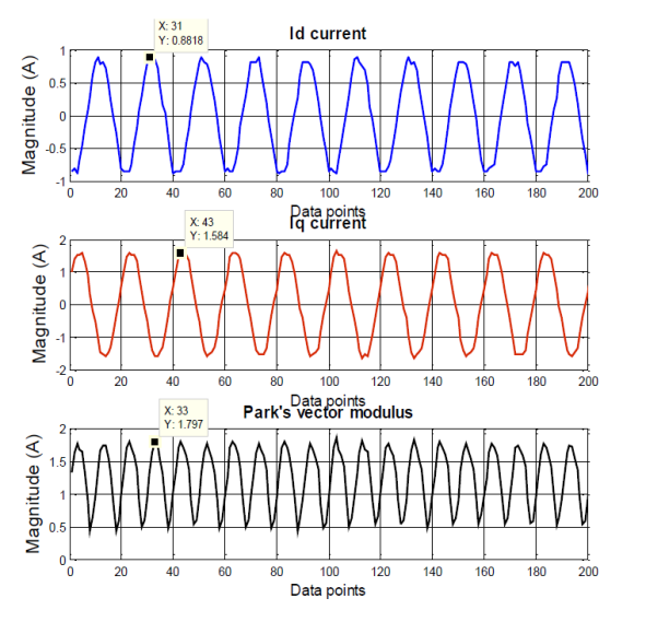
Under ideal conditions, where only the positive‑sequence component is present, the Park vector should exhibit a constant magnitude.
In real machines, however, a slight natural imbalance always exists. This small asymmetry produces a low‑amplitude oscillation with a period given by
This inherent imbalance originates from natural imperfections in the motor construction and minor deviations in the power supply.
Such reference measurements are important for induction motor fault diagnosis, as they serve as a baseline for identifying abnormalities under fault conditions.
As discussed earlier, the simultaneous presence of voltage unbalance and mass (mechanical) unbalance can severely affect motor behavior.
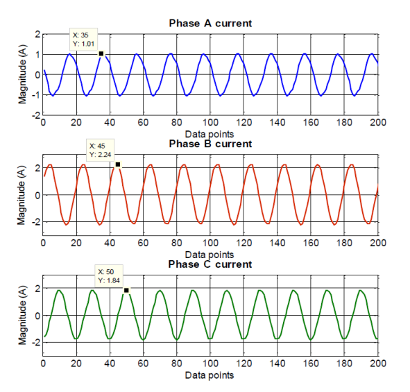
Key observations:
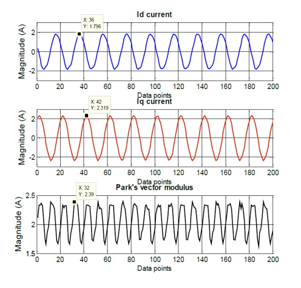
Clear indicators of abnormal behavior are visible:
These variations provide strong signatures for induction motor fault diagnosis under simultaneous mechanical and electrical faults.
The following diagrams compare the peak values of stator currents in both the healthy and faulty conditions. The Current Unbalance Factor (CUF) is calculated according to:
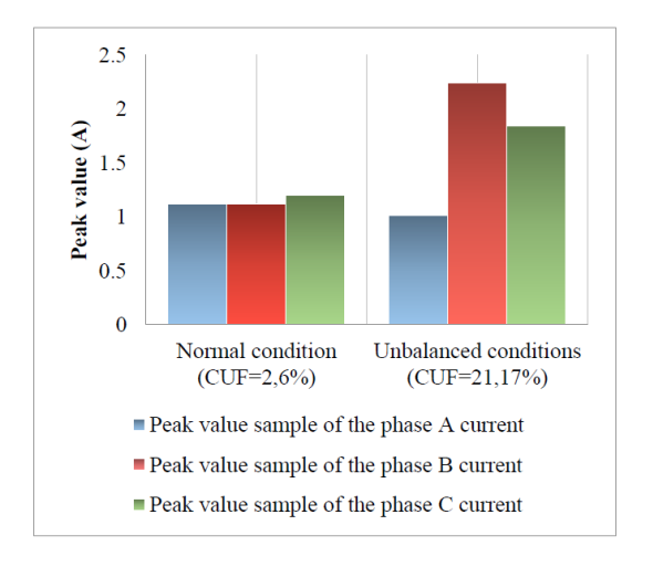
Such a high level of current unbalance leads to several critical consequences:
These symptoms collectively reinforce the importance of induction motor fault diagnosis using stator current signatures.
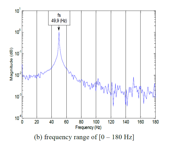
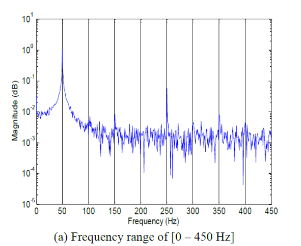
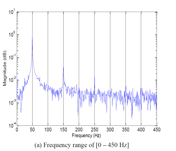
The dominant frequency component corresponds to the supply frequency:
Additional harmonics at 150 Hz, 250 Hz, and 350 Hz are also visible. These are typically caused by:
The Id and Iq components show similar behavior to the three‑phase currents and contain only the main harmonic, as expected in a healthy operating state.
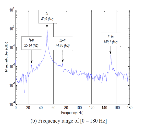
The next figure shows the stator current spectrum of phase A under simultaneous mass unbalance and voltage unbalance. As explained in the theoretical section, mass unbalance generates two characteristic components located symmetrically around the supply frequency .
This experiment was performed under no‑load conditions. According to the results reported by Bouras et al., who used the same motor, the measured no‑load speed at a supply frequency of 50 Hz is:
The rotational frequency is therefore:
Based on Equation (2), the mass‑unbalance characteristic frequencies are:
Thus:
yielding:
According to Equation (3), the dominant signature of voltage unbalance is the third harmonic of the supply frequency:
In the spectrum, this component appears with a significantly increased amplitude, clearly indicating voltage unbalance.
Thus, the spectrum simultaneously exhibits distinct signatures of both mechanical and electrical faults, confirming that Motor Current Signature Analysis (MCSA) can successfully detect combined faults.
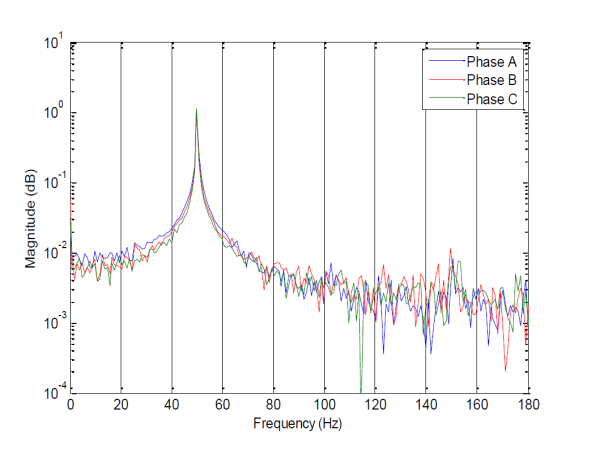
The figure below illustrates the current spectra of all three stator phases under fault conditions in a single combined plot. This representation allows a more comprehensive observation of the overall impact of these faults on motor performance.
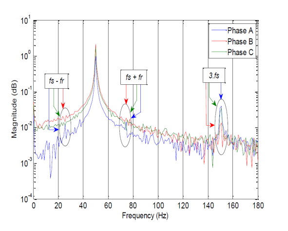
Similarly to the three-phase stator current spectrum, the characteristic frequencies associated with both faults also appear simultaneously in these spectra, exhibiting nearly the same pattern observed in the previous analysis.
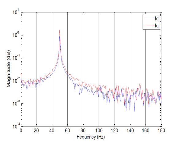
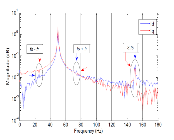
A key point is that the fault characteristic frequencies are more clearly visible and more easily distinguishable in the spectrum than in the spectrum. This is because, according to Equation (1), the component contains all the information from the three-phase stator currents, whereas does not fully possess this characteristic. Therefore, spectral analysis of can provide greater accuracy in fault detection.
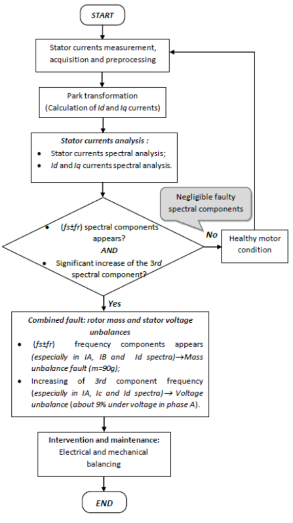
The diagram above summarizes the main steps followed for the detection of combined faults in the induction motor.
The proposed diagnostic procedure consists of the following main stages:
This flowchart demonstrates how the combined use of stator current analysis and Park transformation enables the simultaneous detection of mechanical and electrical faults in an induction motor.
Research studies addressing combined electrical and mechanical faults in induction motors are relatively limited. In this context, the present study experimentally investigates the simultaneous effects of voltage unbalance and mass unbalance on a three-phase induction motor.
To analyze the motor behavior under these abnormal conditions, spectral analysis of the stator currents was first performed. Subsequently, the spectral behavior of the Park transformation components and was evaluated.
Based on the obtained results, the following conclusions can be drawn:
Therefore, the results indicate that the proposed diagnostic method can be successfully implemented in industrial settings for the effective detection of combined faults. This approach is highly relevant for modern motor monitoring and protection systems. For instance, advanced industrial devices, such as the FD110 Induction Motor Protection and Control Unit, which feature real-time current monitoring and phase unbalance detection, can leverage such diagnostic algorithms to significantly enhance the reliability and protection of industrial induction motors.
In general, motor current analysis is considered one of the most practical fault diagnosis techniques in industry because:
In this study, the proposed method successfully detected two different types of faults simultaneously with satisfactory accuracy.
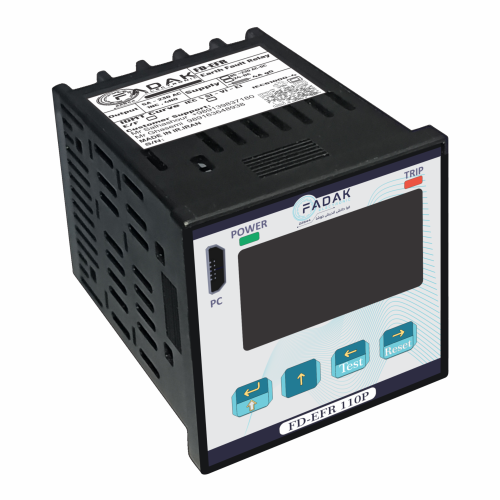
The FD-EFR110P Earth Fault Relay is engineered for highly accurate protection in electrical systems. Using advanced signal-processing techniques, it detects both transient and intermittent earth-fault conditions.
This relay prevents leakage currents and significantly enhances electrical safety by reducing the risk of damage, hazards, and downtime.
Features & Capabilities:
85–260V AC/DC power supply
Digital input for test/reset
1.3" OLED graphical display
Mini USB-B computer interface
Comes with dedicated configuration software
Low power consumption
Available in Lite & Pro versions
Fault waveform recording
Event logging
Transient & intermittent fault detection
Full support for standard protection curves
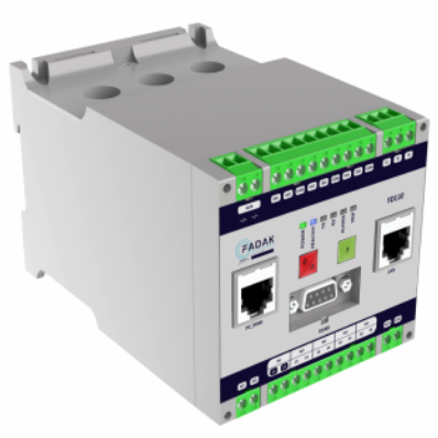
The FD110 Super Induction Motor Controller provides comprehensive and advanced motor protection and management. With precise monitoring and fault diagnosis capabilities, it prevents unwanted shutdowns and ensures stable motor performance. FD110 is suitable for various industrial motors and offers a reliable solution for optimizing operations.
Protection Features:
Overload Protection: Supports class 5 to 40
Overcurrent Protection: IEC standard protection curves
Phase Imbalance & Negative Sequence Protection to prevent abnormal operation
Earth Fault Protection: Supports CBCT or I0 summation methods
Startup & Operating Protection: 48/51LR
Undercurrent Protection to detect abnormal load conditions
Control & Measurement Features:
Compatible with various motor starting methods (Star-Delta, Dahlander, Forward-Reverse)
Built-in timer for advanced motor control
RTD measurement for accurate motor temperature monitoring
4–20mA analog output for integration with control systems
RS485 Modbus communication for industrial monitoring and control
Input/Output Specifications:
Power Supply: 85~260V AC/DC
6 digital inputs, 5 digital outputs
Direct connection up to 100A (above 100A requires external CT)
Key Advantage:
This system provides a complete solution for motor monitoring and protection, enabling optimal management and increasing system reliability.

